


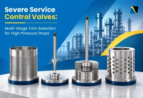
A control valve dissipates pressure energy by restricting flow. Under normal conditions, standard trim handles this duty. However, high pressure drops can create severe operating conditions, including liquid cavitation, excessive gas velocity, noise, and vibration. Flashing can also occur when downstream pressure falls below the liquid’s vapor pressure.
Multi-stage trim addresses high pressure drops by distributing pressure reduction across successive restrictions rather than concentrating it at one point. This helps control cavitation risk, fluid velocity, and noise.
Selecting the right trim requires evaluating fluid properties, operating conditions, pressure distribution, and the dominant damage mechanism. This guide covers the key engineering considerations for multi-stage trim selection, drawing on established ISA and IEC methods and Mascot Valves’ severe-service trim designs.
Severe-service control valves handle demanding conditions where high pressure drops can cause cavitation, excessive noise, vibration and erosion. Multi-stage trim distributes pressure reduction across several restrictions to control these effects. Selecting the right trim requires evaluating Cv, cavitation risk, choked flow, noise, fluid properties and operating range. Different designs address different duties, while flashing and solids-laden service require additional consideration. Mascot’s CavFlo, MegaFlo, TaperFlo and VcFlo offer specific approaches to these challenges.
What Defines a Severe Service Control Valve?
A control valve operates in severe service when process conditions can damage conventional trim or affect control performance. Common conditions include
An important distinction is high inlet pressure versus high differential pressure.
High inlet pressure influences the valve’s pressure-containing requirements, which engineers assess using applicable pressure-temperature ratings under ASME B16.34. High differential pressure creates throttling demands that may require specialized trim to control cavitation, noise, and fluid velocity.
For example, a Class 2500 valve with a modest pressure drop may use conventional trim, while a lower-pressure-class valve experiencing cavitation may require anti-cavitation trim.
Severe service depends on the actual operating conditions, not pressure class or differential pressure alone.
Why High Pressure Drops Cause Problems in Conventional Control Valve Trim
Conventional control valve trim often concentrates pressure reduction at a single throttling point. At high differential pressures, this can create excessive local velocities, cavitation, control valve noise, and vibration.
Vena Contracta, Pressure Recovery and Local Pressure Drop
Fluid accelerates as it passes the throttling point of a valve. Just downstream, it reaches the vena contracta, the narrowest point of the flow stream, where velocity peaks and pressure falls to its lowest value. The fluid then slows, and part of the pressure recovers before the outlet.
The outlet pressure therefore hides how far pressure fell inside the valve. A single-stage trim with high pressure recovery can pull local pressure well below the outlet pressure (P2). The liquid pressure recovery factor (FL) describes this behavior for sizing. A higher FL means less recovery and a shallower dip below P2. FL helps predict choked flow, but it does not predict cavitation damage on its own.
Cavitation and Flashing in Liquid Service
Cavitation occurs when local liquid pressure falls below vapor pressure, forming vapor bubbles. As pressure recovers, these bubbles collapse. Repeated collapse near metal surfaces can cause pitting, erosion, noise and vibration.
Flashing occurs when outlet pressure remains below vapor pressure, allowing a liquid-vapor mixture to continue downstream. Unlike cavitation, flashing primarily causes damage through high-velocity two-phase flow.
The distinction between cavitation and flashing matters because suitable trim can prevent or reduce cavitation, but cannot eliminate sustained flashing under those outlet conditions.
Aerodynamic Noise and High Velocity in Gas and Steam Service
Gas and steam do not cavitate, but a high pressure ratio drives velocity toward sonic at the vena contracta. Turbulence and shock cells in the jet generate aerodynamic noise, which travels downstream and radiates through the pipe wall.
Noise and vibration often become a problem well before velocity reaches sonic. For a fixed valve opening and fixed upstream pressure, temperature and fluid composition, choked flow limits the mass flow rate; reducing downstream pressure further does not increase that mass flow rate. High acoustic energy and flow-induced vibration can cause fatigue at downstream branches or welded attachments and damage valve accessories. For high-energy gas letdown, assess piping vibration risk separately from the external noise requirement.
How Multi-Stage Control Valve Trim Reduces Pressure and Velocity
Multi-stage trim distributes a large pressure drop across several restrictions instead of concentrating it at one point. This helps control local pressure, fluid velocity and energy dissipation.
Single-Stage vs. Multi-Stage Pressure Reduction
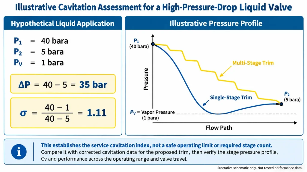
A single-stage trim takes the full pressure drop at one restriction, so the vena contracta pressure dips deep and jet velocity runs high. A multi-stage trim passes the flow through a series of restrictions and expansions. Each stage takes part of the pressure drop, helping reduce local pressure depression and peak fluid velocity compared with single-stage throttling.
Serial stages divide the pressure reduction; multiple parallel holes or paths divide the flow. A cage containing many holes is not necessarily a multi-stage pressure-reduction trim.
Trim designers use two strategies against cavitation. Some staged trims prevent cavitation by keeping the minimum local pressure above vapor pressure at each stage. Impinging-jet trims allow vapor bubbles to form but direct their collapse away from metal surfaces. Many severe service designs combine both.
Pressure Distribution Across Multiple Stages
Pressure drop does not have to be equal across stages. Some designs distribute it evenly, while others use changing flow areas to control pressure and velocity as the fluid moves downstream.
The distribution depends on fluid properties, pressure recovery and trim geometry. For gas and steam service, stage areas and pressure ratios must also accommodate fluid expansion.
Adding more stages can increase flow resistance, reduce available Cv or complicate maintenance. Engineers must therefore select the stage arrangement based on cavitation, noise and velocity requirements while maintaining adequate flow capacity across the operating range.
Types of Severe Service Control Valve Trim and Their Applications
Severe-service trims use different flow paths to control cavitation, noise and velocity. The appropriate design depends on the fluid, pressure drop and operating conditions.
| Trim Type | How It Works | Best Suited To | Main Limitation |
|---|---|---|---|
| Standard single-stage cage or plug | One principal throttling point | General control service where conventional trim meets operating limits | High local velocity at severe pressure drops |
| Drilled-hole anti-cavitation cage | Controls local pressure; impinging-jet designs direct bubble collapse away from metal | Cavitating liquids | Small holes can plug with solids |
| Multi-step axial or stepped plug | Series of expansions and contractions along the flow path | High-pressure-drop liquid service, particularly low flow | Solids tolerance depends on passage clearance |
| Multi-hole, multi-stage noise cage | Splits flow into small streams and reduces pressure gradually | Gas and steam letdown | Primarily designed for aerodynamic noise control, not liquid cavitation |
| Stacked-disk or labyrinth velocity-control trim | Tortuous, multi-path flow with staged pressure reduction | Very high pressure drop in liquid and gas service | Passage complexity, solids tolerance and available Cv |
Downstream diffusers or plates provide another option for gas noise reduction. Installed after the control valve, they share the total pressure drop with the valve. However, they are separate devices rather than internal trim and require sizing across the operating range.
Flashing and Solids-Laden Service Limitations
Multi-stage trim cannot eliminate flashing when P2 remains below Pv. In flashing service, the focus shifts to managing the vapor: angle-body valves discharging into an enlarged outlet, flow directions that keep the mixture away from the body wall, and hardened trim and body materials.
Solids create a different challenge. Narrow multi-stage trim passages can trap particles or experience accelerated erosion under abrasive flow. For solids-laden service, consider particle size, concentration, and the smallest flow passages. Select trim with adequate clearance or self-cleaning flow paths while maintaining the required pressure-reduction capability.
Need the right severe-service trim for your actual pressure-drop conditions?
Discuss Your ApplicationMulti-Stage Valve Trim Selection: A Step-by-Step Engineering Method
Severe-service trim selection requires checking hydraulic performance, cavitation, noise and mechanical limits across the complete operating range.
Step 1: Establish the Complete Operating Conditions
Collect data for minimum, normal, maximum, startup and credible upset conditions. Record P1, P2, flow rate with units and flow basis, inlet temperature, fluid phase, and upstream and downstream pipe sizes and schedules.
For liquids, include specific gravity, viscosity, vapor pressure (Pv) and critical pressure (Pc) for FF calculations. For gases, include molecular weight, specific heat ratio (γ) and compressibility factor (Z).
For solids-laden service, specify maximum particle size, concentration and abrasiveness. Identify dissolved gas and two-phase inlet conditions, as conventional single-phase sizing methods may not apply. Startup or low-load conditions can produce the highest ΔP.
Step 2: Determine Flow Capacity and Check for Choked Flow
Begin with control valve sizing to calculate the required flow coefficient (Cv) using the applicable ANSI/ISA-75.01.01 or IEC 60534-2-1 sizing methods.
For liquids, assess the choked pressure drop. For a line-sized valve without attached reducers:
ΔPchoked = FL²(P1 − FF × Pv), where FF is the liquid critical pressure ratio factor.
P1 and Pv must be absolute pressures in consistent units; Pv is evaluated at inlet temperature. Use the applicable FL at the selected travel. For turbulent-liquid sizing, use the lesser of actual ΔP and the applicable choked sizing ΔP; include attached-fitting corrections where required.
For gases, compare the pressure drop ratio (x = ΔP/P1) with Fγ × xT. Apply the appropriate piping correction factors where required.
P1 is absolute pressure, Fγ = γ/1.4, and xT is the trim’s choked pressure-drop-ratio factor; use the applicable xTP for attached fittings.
The pressure-ratio check alone does not establish gas flow capacity. Cv sizing must also account for the gas expansion factor (Y), inlet temperature (T1), compressibility (Z) and flow basis terms. For multi-stage trim, use manufacturer-validated sizing methods and data rather than applying a generic single-stage factor.
Use the selected trim’s flow coefficients and confirm sufficient capacity and controllable travel across all operating cases.
Step 3: Assess Cavitation Risk in Liquid Service
Calculate the service cavitation index as defined in ISA RP75.23:
σ = (P1 − Pv) / (P1 − P2),
Use consistent absolute pressures for P1, P2 and Pv, with Pv at the applicable liquid temperature.
A lower sigma means a higher cavitation risk. Compare the service sigma with the trim’s tested sigma at the relevant cavitation level, such as incipient, constant or incipient damage, and apply the RP75.23 corrections for size and pressure where applicable.
For comparable corrected data and the chosen cavitation level, a service sigma below the relevant trim threshold indicates that level has been exceeded; do not mix incipient, damage and recommended-service limits.
For multi-stage trim, assess cavitation at each stage using the actual pressure profile and trim-specific performance data. The governing stage depends on the trim geometry and operating conditions. Avoid applying one rule-of-thumb sigma value to every trim. Tested data for the specific geometry give a more reliable answer.
Step 4: Evaluate Noise and Exit Velocity
Predict aerodynamic noise with IEC 60534-8-3 and hydrodynamic noise with IEC 60534-8-4. Compare the results with the plant limit, often specified as 85 dBA at 1 m from the pipe. Compare predicted external sound pressure with the project-specified limit at its defined measurement location and operating case. A limit of 85 dBA at 1 m from the downstream pipe surface is one possible project requirement, not a universal valve acceptance criterion. Assess piping fatigue risk separately. Check valve outlet velocity as well, because high outlet velocity can regenerate noise downstream of a well-designed trim.
Here, velocity head refers to pressure-form kinetic energy (ρV²/2), calculated using the fluid density and velocity at the specified trim-stage exit, not the valve pressure drop or downstream pipe velocity. Apply this criterion only where required by the approved project or manufacturer specification.
Step 5: Set the Trim Arrangement, Number of Stages and Operating Range
Choose the trim type from the dominant problem found in Steps 3 and 4. Then set the number of stages and pressure distribution using trim-specific cavitation, noise and velocity criteria across all operating cases. Mascot’s Vc-Flo trim, for example, uses enough discrete stages to hold liquid trim exit velocity below 23 m/s (75 ft/s).
Recheck capacity once the stages are set. Additional stages can reduce available Cv and may require a larger valve body, depending on the trim design. Confirm controllability at minimum flow, particularly where significant throttling occurs near the seat, and check passage size against the solids content.
Step 6: Confirm Valve Assembly Requirements
Trim selection must also account for mechanical and shutoff requirements.
Verify the following:
These checks help confirm that the complete valve assembly can operate across the specified conditions, not merely pass the required flow.
Unsure whether your selected trim provides enough capacity across all operating conditions?
Discuss Your RequirementsControl Valve Trim Material Selection for High Pressure Drops
Trim material selection must account for erosion, cavitation, corrosion, and operating temperature. The following are material examples, not interchangeable recommendations. Confirm the exact grade, heat treatment, coating or binder system, fluid chemistry, temperature and Mascot-approved construction for the selected configuration. Common options include:
Hardness slows damage but does not stop it. No trim material is immune to cavitation damage, so material supports the hydraulic design rather than replacing it.
Specify the required ANSI/FCI 70-2 leakage class and test conditions separately from trim material. Metal-seated and soft-seated designs can meet different classes depending on their engineered construction; confirm the selected valve’s tested rating and operating limits.
Typical High-Pressure-Drop Control Valve Applications
Boiler Feedwater and Pump Minimum-Flow Recirculation
Minimum-flow recirculation valves return water from the pump discharge to the deaerator or suction tank, often dropping nearly the full pump head across one valve. Hot feedwater combined with a large pressure drop and relatively low downstream pressure can produce a low cavitation index (σ) and severe cavitation.
These valves usually need multi-stage anti-cavitation or velocity control trim with tight shutoff, since leakage wastes pump energy and erodes the seat. Where feedwater regulating valves also handle startup duty, they must maintain accurate low-flow control under potentially high differential pressure. For a broader application discussion, see Mascot’s boiler feedwater control valve guide.
Steam and Gas Pressure Letdown
Steam letdown, turbine bypass and gas pressure-reducing duties can combine high pressure ratios with large flows, making aerodynamic noise and vibration major risks. Multi-hole noise-attenuation or velocity-control trim, sometimes with a downstream diffuser, can help meet specified noise limits. Where letdown steam also needs temperature control, a desuperheater such as Mascot DeFlo can be installed downstream of the pressure-reducing valve.
Chemical and Petrochemical Liquid Letdown
High-pressure separator letdown, amine letdown and hydrocarbon level control often release dissolved gas or flash light components as pressure falls. Engineers must assess cavitation, flashing and outgassing, which can occur together and may require different valve and trim features. Material compatibility and erosion from entrained catalyst or sand often matter as much as the pressure drop.
Common Mistakes in Severe-Service Trim Selection
Several selection errors can reduce valve performance even when the nominal pressure rating and Cv appear correct.
Final selection should reflect the complete operating envelope and the performance data of the specific trim.
Need to review an existing severe-service valve before changing the trim?
Contact MASCOT ValvesMascot Severe Service Trim Options for High Pressure Drops
With over 50 years of valve manufacturing experience, Mascot Valves provides control valves and severe-service trims for demanding process conditions. Established in 1972, the company operates in Ahmedabad, India, and Houston, Texas, with ISO 9001:2015, ISO 14001:2015 and ISO 45001:2018 management-system certifications.
For high-pressure-drop applications, the GFlo-globe control valve supports specialized trims for cavitation, noise and velocity control.
| Trim | Design Approach | Service | Notes |
|---|---|---|---|
| CavFlo | Drilled seat retainer with opposing holes; jets meet at the retainer center so bubbles collapse away from metal | Cavitating liquids | 1–6 stage configurations; balanced or unbalanced; flow over the plug; fits standard GFlo bodies; requires clean fluid |
| TaperFlo | Tapered stages between plug and seat create repeated expansion and contraction | Low-flow, high-pressure-drop liquid applications | Flow under the plug; combines staging with hard-facing; self-cleaning flow path for selected solids-laden applications |
| MegaFlo | Splits gas flow into many small streams and reduces pressure gradually | Gas and steam noise reduction | 1–7 stage configurations; downstream noise reduction plates available |
| VcFlo (VC trim) | Multi-stage, multi-path velocity control through repeated direction changes | Liquid and gas service, atmospheric vents | VC liquid-service design criterion: trim exit velocity below 23 m/s (75 ft/s), subject to application-specific verification; separate VC vent stack option |
Published stage ranges describe available trim configurations and do not guarantee suitability for every valve size or operating condition. Flow direction, body compatibility, downstream plate arrangements and vent-stack options must be verified against the applicable product documentation.
For erosive or solids-laden service, Mascot also offers the EFlo-eccentric plug valve and VFlo segmented V-notch ball valve. Suitability for solids handling does not by itself establish suitability for the full pressure letdown: verify cavitation, pressure recovery, velocity, erosion, shutoff and actuator loads for the selected rotary-valve configuration.
The QuickFlo shut-off ball valve serves on/off isolation duties rather than continuous pressure letdown.
No single valve or trim suits every severe-service application. The correct selection depends on ΔP, fluid properties, cavitation risk, noise limits, flow capacity and maintenance requirements.
Selecting a control valve for high-pressure-drop or severe-service conditions? Share your operating parameters with Mascot’s engineering team to identify a suitable valve and trim configuration. Discuss Your Application.
FAQ
1) When is multi-stage trim required in a control valve?
Consider multi-stage trim when conventional trim cannot adequately manage cavitation, excessive velocity, aerodynamic noise, or other severe pressure-reduction effects. The decision depends on operating conditions and valve performance data rather than a fixed differential-pressure threshold.
2) How is the number of pressure-reduction stages determined?
Stage count depends on ΔP, fluid properties, internal pressure distribution and trim-specific cavitation, noise and velocity limits. Engineers must also verify Cv and controllability across the operating range. Published stage ranges do not establish the required configuration for a particular duty.
3) Can multi-stage trim eliminate cavitation and flashing?
Suitable multi-stage trim can prevent cavitation under specified conditions or reduce damage by controlling bubble collapse. It cannot eliminate sustained flashing when P2 remains below Pv. Flashing service requires suitable flow-path geometry and erosion-resistant materials.
4) Can multi-stage trim handle fluids containing solids?
Some multi-stage trims can handle suspended solids, depending on particle size, concentration and passage geometry. Mascot’s TaperFlo incorporates a self-cleaning flow path for selected applications, while fine-passage designs may be susceptible to plugging.
5) What are the signs that the installed trim is unsuitable for the pressure drop?
Possible signs include excessive noise, vibration, recurring trim erosion, increasing seat leakage and unstable valve movement. These symptoms may also result from actuator problems, positioner performance, installation conditions or changing process requirements. Confirm the cause through operating-data review, diagnostics and inspection before changing the trim.

