


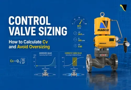
A control valve can pass the required maximum flow and still be the wrong valve for the application. If it operates near shutoff at normal load, the loop hunts. If the pressure drop exceeds the choked flow limit, increasing demand produces noise and trim erosion, not more flow. If the valve takes an insufficient share of the total system pressure drop, the installed flow characteristic distorts, and no amount of retuning recovers the lost control resolution.
Most of these failures share a single root cause: the Cv calculation covered one condition, at one operating point, without verifying that the selected valve can control across the full process range.
This article explains the complete control valve sizing sequence: process data, valve pressure drop, liquid Cv calculation, gas and steam sizing, correction factors, trim selection, three-point validation, and oversizing prevention.
A reliable control valve selection does not stop at Cv. Engineers must calculate capacity, check actual valve ΔP, apply correction factors, select the correct trim, validate travel across the full operating range, and review cavitation, noise, actuator, and shutoff requirements.
What Cv Means in Control Valve Sizing
Cv is the valve flow coefficient. It represents the number of US gallons per minute of water at 60°F that will pass through a fully open valve with a 1 psi pressure drop.
A higher Cv means the valve can pass more flow at the same pressure drop. A lower Cv means the valve creates more restriction. However, Cv does not confirm whether the valve will control well in actual service. It only describes flow capacity under defined conditions.
Cv vs Kv: Same Flow Capacity, Different Unit Conventions
Cv and Kv both express valve capacity. Cv is commonly used in ANSI/ISA and US-based projects. Kv is common in IEC, DIN, and metric specifications.
| Coefficient | Meaning |
|---|---|
| Cv | US GPM of water at 60°F with 1 psi pressure drop |
| Kv | m³/h of water with 1 bar pressure drop |
Common conversion:
Kv = 0.865 × Cv
Cv = 1.156 × Kv
Rated Cv, Inherent Cv, and Installed Capacity
Rated Cv usually refers to valve capacity at full travel under standard test conditions. Inherent Cv describes the relationship between travel and flow capacity at constant pressure drop. Installed capacity describes what the valve actually delivers in the process system, where pressure drop changes with flow.
This difference matters because two valves with the same rated Cv can behave differently after installation.
Start with Complete Process Data, Not the Cv Formula
A Cv calculation is only as accurate as the process data behind it. Sizing from one maximum-flow case often leads to oversizing because it does not show how the valve behaves at normal or minimum load.
Required Inputs for Every Sizing Case
| Required Input | Why It Matters |
|---|---|
| Fluid type, phase, and composition | Determines liquid, gas, steam, slurry, or two-phase sizing method |
| Flow at minimum, normal, and maximum conditions | Establishes capacity, controllability, and turndown requirements |
| Upstream and downstream pressure at each condition | Determines actual valve ΔP, not equivalent to pump or compressor head |
| Temperature | Affects density, vapour pressure, viscosity, and gas compressibility |
| Specific gravity, vapour pressure, viscosity | Required for liquid Cv, cavitation, and FR correction calculations |
| Molecular weight, Z, and k | Required for gas and steam sizing per ANSI/ISA-75.01.01 |
| Pipe size, schedule, reducers, and fittings | Required to calculate Piping Geometry Factor FP |
| Shutoff class, fail action, noise limit | Determines trim type, actuator spec, and accessory selection |
Why Minimum, Normal, and Maximum Conditions Must Be Evaluated
Maximum flow confirms capacity and actuator adequacy. Normal flow confirms the valve controls stably at the condition it operates at most of the time. Minimum flow confirms the valve does not operate in the near-shutoff region where controllability degrades and trim wear accelerates. Collect all three before opening a sizing tool.
Step 1: Determine Actual Valve Pressure Drop and Valve Authority
Valve ΔP Is Not the Same as Pump or Compressor Differential
Pressure is shared across every element in the circuit: piping, fittings, exchangers, filters, strainers, and all other in-line restrictions. Using pump head as valve ∆P overstates the pressure drop available across the valve, understates the required Cv, and can result in an oversized valve.
Valve ΔP changes with flow and must be calculated at each operating condition from a system hydraulic analysis. At high flow, pipe losses usually increase, so valve ΔP reduces. At low flow, pipe losses reduce, so valve ΔP increases.
In most liquid systems, valve ΔP is lowest at maximum flow as pipe friction losses are highest. The sizing engineer must confirm valve ΔP at each operating case through hydraulic analysis rather than assuming one fixed value.
Cavitation, flashing, and liquid choking must be evaluated at each operating condition using the actual P1, P2, vapour pressure, and valve-specific FL. The governing standard is ANSI/ISA-75.01.01 (IEC 60534-2-1 Mod).
Valve Authority and Its Effect on Installed Characteristic
Valve authority is the ratio of valve ΔP to total circuit ΔP:
Valve authority = ΔP valve ÷ ΔP total circuit
When authority is low, the installed flow characteristic diverges from the inherent characteristic as flow changes. Low valve authority can distort the installed characteristic, increase loop gain in certain travel regions, and make stable control difficult even with correct positioner tuning.
Treat Travel and Authority Targets as Screening Guidance
Pressure drop allocation targets and travel percentage rules are preliminary screening values. Accept or reject a selection based on the specific Cv-versus-travel curve at the actual installed operating conditions, the system hydraulic model, and the control performance requirements.
Need help translating your process conditions into the right control valve sizing basis?
Talk to Our Engineering TeamStep 2: Calculate Required Cv for Liquid Service
The Core Liquid Cv Formula
For turbulent, non-flashing, non-cavitating, single-phase liquid flow per ANSI/ISA-75.01.01:
Cv = Q × √(SG ÷ ΔP)
Where Q = flow in US GPM, SG = specific gravity relative to water at 60°F, ΔP = valve differential pressure in psi.
ΔP is the system-derived valve differential at the operating flow condition. Calculate it separately at each of the three operating conditions.
Use a Three-Condition Sizing Method
Calculate required Cv at maximum, normal, and minimum flow. Select the valve on the maximum required Cv. Then verify the Cv-versus-travel curve at normal and minimum flow before accepting the selection.
Worked Example: Cooling Water Service
| Condition | Flow (GPM) | Specific Gravity | Valve ΔP (psi) | Required Cv |
|---|---|---|---|---|
| Minimum | 80 | 1.0 | 19 | 18.4 |
| Normal | 150 | 1.0 | 15 | 38.7 |
| Maximum | 200 | 1.0 | 12 | 57.7 |
Select on a rated Cv at or above 57.7. Verify that normal flow (Cv 38.7) and minimum flow (Cv 18.4) both fall in a stable, controllable travel range on the manufacturer’s published Cv-versus-travel curve. A rated Cv significantly above 57.7 without a trim-size or outlet-velocity justification is likely to produce an oversized valve.
When the Basic Liquid Formula Does Not Apply
Additional calculations are required for: high-viscosity liquids where the valve Reynolds number indicates transitional or laminar flow (FR correction); cavitating service (FL² × (P1 − FF × Pv) check); flashing; choked liquid flow; two-phase inlet conditions; and pipe reducers or expanders (FP correction).
Step 3: Calculate Cv for Gas and Steam Service
Why Compressible-Flow Sizing Is Different
Gas and steam are compressible. Density, specific volume, and velocity all change as pressure drops through the restriction. The liquid Cv formula produces a meaningless result for compressible fluids. Use the ANSI/ISA-75.01.01 or IEC 60534-2-1 equation set for gas and steam.
Key Variables in Gas and Steam Sizing
| Variable | What It Governs |
|---|---|
| Absolute inlet pressure P1 (psia, not psig) | Base pressure for all gas sizing equations; gauge pressure produces incorrect Cv |
| Temperature (Rankine for US units) | Affects gas density and compressibility |
| Molecular weight | Gas density relative to air |
| Compressibility factor Z | Non-ideal gas behaviour at elevated pressure |
| Specific heat ratio k | Gas expansion behaviour through the restriction |
| Expansion factor Y | Decreases as pressure drop ratio increases; limited to 0.667 at choked flow. Values below 0.667 must not be used in the sizing equation |
| Terminal pressure drop ratio factor xT | Valve-specific from manufacturer test data; defines the ΔP ratio at which choked flow begins. Globe valves typically carry higher xT values than rotary valves, meaning they use more of the available pressure drop before reaching the choked limit |
Choked Flow Check in Gas Service
Choked flow occurs when the pressure drop ratio x = ΔP ÷ P1 reaches or exceeds Fk × xT, where Fk = k ÷ 1.40. Beyond this point, increasing ΔP does not increase flow. It generates aerodynamic noise, vibration, and trim erosion instead. Do not apply the unchoked gas equation to a valve operating at or past its xT limit.
Steam Sizing Considerations
Confirm saturated or superheated conditions before selecting the equation set. Use absolute pressure throughout. For high-pressure steam letdown, predict aerodynamic noise per IEC 60534-8-3 as part of the sizing exercise, not as a post-selection check.
Step 4: Apply the Correction Factors That Determine Real Installed Capacity
Three correction factors govern real installed capacity and are omitted from most sizing calculations.
FL: Liquid Pressure Recovery Factor
FL measures how much pressure the valve recovers downstream of the vena contracta, which is the point of maximum velocity and minimum pressure inside the valve. The choked liquid ΔP limit is:
ΔP choked = FL² × (P1 − FF × Pv), where FF = 0.96 − 0.28√(Pv/Pc)
Where P1 is upstream absolute pressure and Pv is fluid vapour pressure at operating temperature.
If actual valve ΔP approaches or exceeds this limit, the service has entered a liquid choking or cavitation-risk condition and requires detailed evaluation using valve-specific data.
Published FL values are typically higher for globe valves than for butterfly valves. These ranges vary by valve design, trim geometry, travel position, and flow direction. Use manufacturer specific FL data for final selection. Two valves with identical rated Cv but different FL values have very different safe pressure drop limits in liquid service.
A properly selected globe valve can generally accommodate higher liquid pressure drops than many rotary valve designs before reaching their cavitation limits, but the actual limit must be established from valve-specific FL data and operating conditions.
FP: Piping Geometry Factor
FP corrects for pressure losses in reducers and expanders when the valve body size differs from the pipe. When body and pipe match, FP = 1.0. When reducers are present, FP reduces the effective Cv of the assembly below the rated valve Cv. A valve selected without FP may be unable to deliver the required flow after installation. Per ANSI/ISA-75.01.01 Section 4.3, calculate or confirm FP from manufacturer data whenever the valve-to-pipe diameter ratio differs from 1:1.
FR: Reynolds Number Factor for Viscous Service
FR should be evaluated when fluid viscosity may push flow into transitional or laminar behaviour. Approximately 40 centistokes is a useful early screening flag, not a hard calculation trigger. Final determination uses the valve Reynolds number at the actual operating condition.
For most process fluids, FR = 1.0. For heavy crude oil, polymer melt, molasses, and slurry services, omitting FR produces a valve that is undersized at actual operating viscosity. This correction is particularly relevant for EFlo eccentric plug valve applications in erosive and slurry service and VFlo segmented V-notch ball valve applications in viscous or fibrous media.
Distinguish Cavitation, Flashing, and Liquid Choking
Cavitation: Vapour bubbles form when local pressure falls below vapour pressure and collapse when pressure recovers downstream, eroding metal surfaces. Cavitation risk should be evaluated using valve-specific FL data, vapour pressure, outlet pressure, and actual valve ΔP. The choked liquid pressure-drop limit provides a practical screening check.
Flashing: Vapour bubbles form at the vena contracta and remain as vapour because outlet pressure does not recover above vapour pressure. Produces two-phase flow downstream and requires a separate sizing approach.
Liquid choking: A capacity limit at the choked ΔP threshold. Beyond this point, reducing downstream pressure does not increase flow. When liquid choking limits the available pressure drop, the sizing calculation must account for the choked-flow limit rather than assuming that additional pressure drop will produce additional flow.
Also Read: Mitigating Cavitation and Flashing: Practical Trim Solutions with Mascot Valves
Looking for the right sizing solution for demanding liquid-service conditions?
Contact MASCOT ValvesStep 5: Select Body Size, Trim Cv, and Flow Characteristic
Body Size Is Not the Same as Trim Cv
Body size determines the nominal connection size and affects face-to-face dimensions. Pressure class is selected separately based on body design, material, end connection type, and the applicable pressure-temperature rating standard.
Trim size determines flow capacity. The Mascot GFlo – globe control valve accepts full-area, reduced, and integral trim configurations within the same body, with all seat rings and plugs interchangeable within a given body size and pressure class.
Select the trim to satisfy the required Cv. Select the body to accommodate the trim within the applicable pressure class and to meet outlet velocity requirements. Never select by pipe size alone.
Select the Rated Cv and Trim Configuration
The selected rated Cv should equal or slightly exceed the maximum required Cv. If the Cv-versus-travel check at normal flow reveals an oversized condition, evaluate a reduced-Cv trim in the same body before changing the body size or valve type. Trim changes are less disruptive and less costly than body changes.
Select the Correct Inherent Flow Characteristic
Equal percentage: Cv changes by a fixed percentage per unit of travel. The standard choice where system piping losses cause valve ΔP to vary with flow. Produces a near-linear installed characteristic in those conditions.
Linear: Cv changes in direct proportion to travel. Suited where valve ΔP remains comparatively stable across the flow range.
Quick opening: Large Cv increase at low travel. For on/off service only, not modulating control.
Select Valve Type Based on Service Requirements
| Service Condition | Appropriate Valve Type |
|---|---|
| High pressure drop, accurate throttling | GFlo – globe control valve |
| Cavitation-prone liquid service | GFlo with CavFlo – anti-cavitation trim |
| High-pressure gas or steam letdown | GFlo with MegaFlo – noise attenuation trim |
| Erosive service, slurries, solids-laden fluids | EFlo – eccentric plug valve , rangeability greater than 160:1 |
| Viscous, fibrous, or pulp media | VFlo – segmented V-notch ball valve , 300:1 rangeability |
| Light throttling, high flow, large pipe sizes | DiskFlo – double offset butterfly valve |
| Position feedback and limit indication | XFlo – position transmitter and limit switch |
| Pneumatic or electro-pneumatic positioning | HiFlo – pneumatic positioner or SmartFlo – HART digital positioner |
Step 6: Validate Against Minimum, Normal, and Maximum Flow
Verify Capacity at Maximum Flow
Check selected trim Cv against the required Cv at maximum flow. Confirm there is adequate travel reserve for realistic demand increases. Verify that actuator thrust (linear valves) or torque (rotary valves) is sufficient to seat the valve against maximum differential pressure at shutoff and to modulate the trim across the full operating range. Check that outlet velocity and applicable noise limits are not exceeded at maximum flow.
Verify Stable Control at Normal Flow
Normal flow is the condition the plant operates at most of the time. Review normal-flow travel on the manufacturer’s Cv-versus-travel curve. Confirm the installed characteristic supports the loop gain required by the control system. Check valve authority. Verify actuator stiffness and positioner response to improve control valve performance at the normal operating travel position.
Verify Controllability at Minimum Flow
Minimum flow is where oversizing becomes visible. Confirm the valve can provide the required Cv at minimum flow at a travel position above its minimum controllable range. Check whether the valve operates too close to shutoff. Assess whether deadband and stiction become process-visible at the minimum travel position. Confirm the required process turndown falls within the valve’s installed rangeability.
If minimum-flow controllability is poor, evaluate reduced trim, a different flow characteristic, a higher-rangeability valve type (EFlo at greater than 160:1, VFlo at 300:1), or a split-range arrangement.
What Happens When a Control Valve Is Oversized?
Signs of Oversizing
The valve operates at very low travel during normal production.
Small controller output changes produce large flow changes and the loop oscillates.
Seat, plug, ball, or disc wear appears earlier than expected.
Positioner retuning improves performance temporarily but does not resolve the underlying instability.
Why Oversized Valves Cause Poor Control
An oversized valve operates in the lower portion of its travel range at normal flow. At low travel, small mechanical movement, deadband, or stiction becomes large relative to the required flow change. The valve cannot resolve small corrections accurately, which drives loop instability.
Stiction and deadband, acceptable at correct sizing, become large enough at low travel to cause limit cycling. In liquid service at high pressure drop, low travel also concentrates fluid velocity at the restriction and increases cavitation risk.
Common Root Causes of Oversizing
Sizing on maximum conceivable flow rather than realistic maximum operating flow
Using incorrect valve ΔP assumptions
Applying safety margins to both flow and ΔP simultaneously
Rounding up to the next body size instead of specifying reduced trim
Not checking the Cv-versus-travel curve at normal and minimum flow
Corrective Options
At the design stage: Recalculate using all three conditions with system-derived ΔP. Specify trim Cv explicitly on the data sheet. Verify travel at normal and minimum flow before releasing the specification.
For installed valves: Confirm whether reduced-Cv trim fits the existing body. GFlo seat rings and plugs are interchangeable within a given body size and pressure class. Where turndown has grown beyond the practical control range, evaluate a characterised trim, a different valve type, or a split-range arrangement.
Dealing with an oversized valve or poor control at normal operating conditions?
Contact UsSevere-Service Checks That Can Change the Final Valve Selection
Cavitation and CavFlo Cavitation-Control Trim
After completing the liquid Cv calculation, evaluate cavitation and choking risk using valve-specific FL data, vapour pressure, outlet pressure, and actual valve ΔP. If the service falls into a cavitation-risk regime and downstream pressure remains above vapour pressure, standard trim may not adequately control the damage mechanism depending on service severity. In such cases, cavitation-control trim should be evaluated using trim-specific sizing data.
Mascot’s CavFlo – anti-cavitation trim uses diametrical flow through opposing holes in the seat retainer wall. As the plug lifts, pairs of holes open progressively. Each hole discharges a liquid jet toward the centre of the retainer, where it meets the opposing jet. Bubble implosion is relocated from metal surfaces into the fluid stream, and the vena contracta forms outside the retainer rather than at the plug-seat restriction.
CavFlo fits standard GFlo – globe valve bodies in pressure-balanced and unbalanced configurations. Sizing must use CavFlo-specific Cv data, as standard GFlo trim Cv tables do not apply. Typical applications include boiler feedwater pressure let-down, condensate control, and high-pressure liquid transfer in refinery and chemical plant service.
Aerodynamic Noise and MegaFlo Noise-Attenuation Trim
For gas and steam service at high pressure drop ratios, predict aerodynamic noise per IEC 60534-8-3 before finalising the selection. In a single-throttling-point globe valve, the full pressure drop concentrates at the vena contracta and gas velocity rises sharply. Mascot’s MegaFlo – noise attenuation trim divides the total flow into multiple small streams through a multi-path, multi-stage design.
Each stream takes a fraction of the total ΔP, keeping gas velocity through each stage below levels that generate high aerodynamic noise. Successive stages also attenuate noise propagating upstream. MegaFlo requires MegaFlo-specific Cv data for sizing. Typical applications include gas pressure letdown, steam conditioning, compressor antisurge, and gas injection control.
Actuator, Shutoff, and Positioner Verification
Cv sizing does not replace actuator sizing. After body, trim, and characteristic are confirmed, verify actuator thrust or torque against maximum shutoff differential pressure, shutoff leakage class per ANSI/FCI 70-2, fail action, positioner type, and ATEX, IECEx, or other applicable hazardous-area approvals as required by project location, site standard, and area classification.
Conclusion
Control valve sizing is complete only when the selected valve is confirmed to control, not just to flow, across the full operating range. Cv calculation gives you required capacity at maximum demand. The three-condition method gives you confidence the valve holds set point at normal load and remains controllable at minimum flow. FL, FP, and FR determine whether the Cv the formula returns is the Cv the valve actually delivers in service.
Oversizing results from compounding assumptions that each seem conservative in isolation. Together they produce a valve that controls badly at the conditions it operates at most of the time.
If you are sizing a control valve for a new project or reviewing an existing installation, Mascot Valves’ engineering team can review your process conditions, identify severe-service requirements, and recommend the appropriate valve body, trim, and actuator configuration. Submit your minimum, normal, and maximum operating conditions to get started.
FAQ
1) What is Cv in control valve sizing?
Cv is the number of US gallons per minute of water at 60°F that flows through a fully open valve with a 1 psi pressure drop, per ANSI/ISA-75.01.01. The metric equivalent is Kv (Kv = 0.865 × Cv), used in EN/IEC project specifications. Cv is bench-measured at full open; in a modulating application, the effective Cv at the operating travel position governs control performance, not the rated maximum.
2) What causes a control valve to be oversized?
The most common causes are sizing on maximum conceivable flow rather than realistic maximum operating flow; using incorrect or unrealistic valve ΔP assumptions at the sizing condition; applying safety margins to both flow and ΔP simultaneously; rounding up to the next body size instead of specifying reduced trim; and not checking the Cv-versus-travel curve at normal and minimum flow.
3) What is valve authority and why does it matter?
Valve authority is the ratio of valve ΔP to total circuit ΔP. When authority is low, the installed flow characteristic diverges from the inherent characteristic as flow and system losses change. Low valve authority can distort the installed characteristic, increase loop gain in certain travel regions, and make stable control difficult even with correct positioner tuning.
4) What is FL and how does it affect cavitation risk in liquid control valve sizing?
FL is the liquid pressure recovery factor. It shows how valve geometry affects pressure recovery after the vena contracta and is used to evaluate liquid choking and cavitation risk. The choked liquid pressure-drop limit is calculated from valve-specific FL and the liquid critical pressure ratio factor FF. If actual valve ΔP approaches or exceeds this limit, cavitation, flashing, and liquid choking must be assessed using manufacturer-specific data. Published FL values are typically higher for globe valves than for butterfly valves, but the final value must come from manufacturer test data for the selected valve and trim.
5) When should cavitation-control or noise-attenuation trim be considered?
Cavitation-control trim should be evaluated when liquid service enters a cavitation-risk regime and downstream pressure remains above fluid vapour pressure. Final selection should use valve-specific FL, outlet pressure, vapour pressure, and trim-specific Cv data.
Noise-attenuation trim applies in gas or steam service where IEC 60534-8-3 noise prediction exceeds the applicable site limit, typically in pressure letdown, steam conditioning, compressor antisurge, and gas injection applications. In both cases, use trim-specific Cv data for final sizing.
6) Why can two valves with the same Cv perform differently in service?
Rated Cv is bench-measured at full open and constant ΔP. Installed performance depends on the valve’s FL, its inherent flow characteristic, valve authority, and actuator and positioner dynamics. Two valves with the same rated Cv but different FL values, different characteristics, or different installed authority can produce very different loop performance at identical process conditions.

