


A control valve may meet the maximum flow requirement but still struggle to maintain stable control at lower flow rates. This makes rangeability and turndown ratio important considerations during valve selection.
Although the two terms are closely related, treating them as interchangeable can lead to incorrect assumptions about a valve’s actual operating range.
Terminology varies between manufacturers, and turndown is sometimes used interchangeably with rangeability. In this article, inherent rangeability refers to the qualifying Cv ratio, while process and installed turndown refer to flow-rate ratios.
Mascot Valves has manufactured control valves since 1972, with experience across different process applications. In this article, we draw on that experience to explain the difference between rangeability and turndown ratio and what engineers should consider when selecting a control valve.
Control valve rangeability measures the ratio of maximum to minimum flow coefficients (Cv) over which a valve maintains its specified inherent flow characteristic. Turndown ratio describes the maximum-to-minimum flow range required by the process or achievable after installation. Published rangeability does not guarantee equivalent installed turndown, as differential pressure, valve sizing, trim characteristics and actuator-positioner performance affect actual control. Engineers must verify Cv, valve travel and controllability at minimum, normal and maximum flow conditions before selecting a control valve.
Control Valve Rangeability: Definition and Calculation
Control valve rangeability describes the range of flow coefficients over which a valve maintains its specified inherent flow characteristic within defined tolerances. It indicates the valve’s inherent throttling capability, not the flow range it can necessarily control after installation.
Inherent Rangeability and Its Formula
Inherent rangeability refers to the valve’s performance under constant differential-pressure conditions, independent of the pressure variations that may occur in an installed system.
According to IEC 60534-2-4:2009, inherent rangeability is determined from the largest and smallest flow coefficients that meet the permissible deviations from the stated inherent flow characteristic for a specific valve configuration. These limits must be supported by the manufacturer’s declared characteristic or test data, consistent with references such as ANSI/ISA-75.11.01, and the largest qualifying Cv may differ from the rated Cv.
Inherent Rangeability (R) = Cv,max ÷ Cv,min
Here, Cv is the valve flow coefficient. One Cv represents a flow of one US gallon per minute of water at 60°F with a 1 psi pressure drop.
For example, if a valve has a maximum qualifying Cv of 50 and a minimum qualifying Cv of 1:
Rangeability = 50 ÷ 1 = 50:1
The valve meets its specified inherent characteristic across this 50:1 range of flow coefficients. Published rangeability does not guarantee equivalent installed turndown. Engineers must also evaluate operating conditions and minimum-flow controllability.
Why Published Rangeability Figures Differ
Two control valves may have the same published rangeability but different low-flow performance. The differences arise from valve design, trim configuration and the basis used to establish the stated ratio.
Key considerations include:
Minimum qualifying Cv is not the same as seat leakage. The former defines the lower limit of the stated inherent rangeability, while seat leakage measures flow through a closed valve under specified test conditions.
When comparing manufacturer datasheets, check the valve configuration and the technical basis of the published rangeability.
Turndown Ratio in Control Valves: Meaning and Calculation
Turndown ratio describes the ratio between maximum and minimum flow rates. In control valve applications, engineers distinguish between required process turndown and installed valve turndown.
Required Process Turndown vs Installed Valve Turndown
These terms describe two different requirements:
Installed turndown depends on pressure drop, valve sizing, actuator and positioner performance. A suitable ratio alone does not guarantee control at all required operating conditions.
Turndown Ratio Formula
Required Process Turndown = Maximum Required Flow ÷ Minimum Required Flow.
Installed Valve Turndown = Maximum Controllable Flow ÷ Minimum Controllable Flow
Compare flows on the same basis. For gases, use mass flow or volumetric flow referenced to the same standard pressure and temperature; do not mix actual and standard volumetric rates.
Unlike inherent rangeability, which uses Cv values, turndown compares flow rates. Changes in differential pressure can make these ratios different.
Rangeability vs Turndown Ratio: Key Differences
The main difference lies in what each ratio measures and how engineers establish it.
| Parameter | Inherent Rangeability | Turndown Ratio |
|---|---|---|
| Meaning | Range of Cv values meeting the stated inherent characteristic | Ratio of maximum to minimum flow rates |
| Formula | Cvmax ÷ Cvmin | Qmax ÷ Qmin |
| Operating basis | Defined inherent valve conditions | Required process conditions or installed operation |
| Main influences | Trim geometry, flow characteristic and characteristic tolerances | Differential pressure, valve sizing, actuator, positioner and system conditions |
| Engineering purpose | Evaluate the valve’s inherent modulation capability | Determine whether the required flow range can be controlled |
IEC 60534-2-4 provides the reference for inherent rangeability. Installed turndown requires an application-specific assessment rather than relying on a catalogue ratio alone.
Need help matching valve rangeability to your actual process turndown requirement?
Talk to Our Engineering TeamRangeability vs Turndown Ratio: A Practical Example
Consider a simplified water-flow application (SG = 1), assuming turbulent, non-choked flow without significant piping-fitting effects.
| Operating Condition | Flow | Valve ΔP | Required Cv |
|---|---|---|---|
| Maximum | 400 gpm | 9 psi | 133.3 |
| Minimum | 20 gpm | 36 psi | 3.33 |
Using Cv = Q × √(SG / ΔP):
Here, Q is in US gallons per minute (gpm), ΔP in psi, and SG is relative density at flowing conditions. This simplified equation applies to turbulent, non-choked liquid flow; gases, viscous/low-Reynolds-number service and attached fittings require the applicable sizing corrections.
Required process turndown = 400 ÷ 20 = 20:1
Required Cv span = 133.3 ÷ 3.33 ≈ 40:1
For the same liquid, the required Cv span can be calculated as.
In this example, the required Cv span is 20 × √(36 ÷ 9) = 40:1. The higher pressure drop at minimum flow makes the required Cv span wider than the process flow turndown.
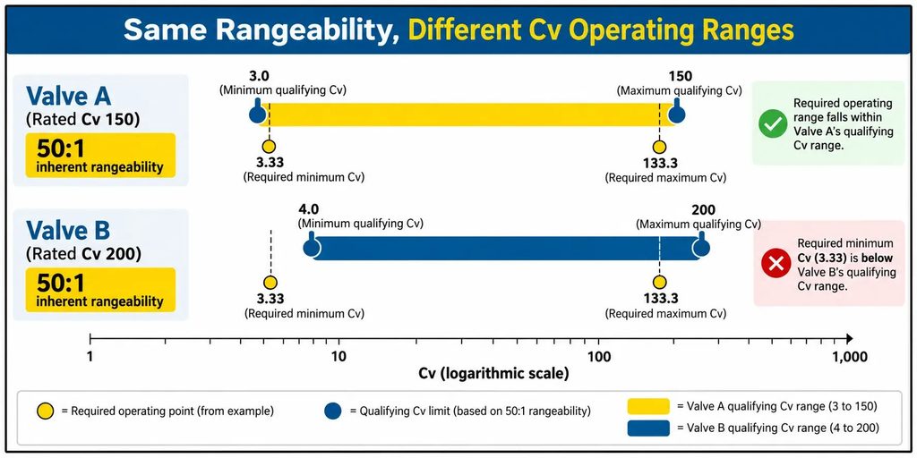
Now compare two hypothetical valves, each with 50:1 inherent rangeability. Assume the manufacturer’s characteristic data confirm that rated Cv equals maximum qualifying Cv.
Both valves have the same published rangeability but different qualifying Cv limits. Valve A is only a preliminary capacity/rangeability screen, not a confirmed selection: its minimum required Cv is just 3.33 versus a qualifying minimum of 3.0. Check the actual Cv-versus-travel curve, control accuracy, normal operating point and any required capacity margin.
Factors Affecting Installed Turndown Ratio
Installed turndown depends on how the valve and its control assembly perform under actual operating conditions. Three factors have a significant influence.
Differential Pressure, Valve Authority and Installed Flow Characteristics
Manufacturers establish inherent flow characteristics at constant pressure drop. In operating systems, pressure drop across the valve often changes with flow.
Valve authority describes the valve’s pressure-drop relationship within a defined hydraulic circuit. For a simple series circuit with the valve fully open at design flow, it can be expressed as:
Valve Authority (a) = ΔPvalve ÷ (ΔPvalve + ΔPrest)
Here, ΔPrest is the pressure drop across the remaining circuit at the same flow. Low valve authority can distort the installed flow characteristic, making an inherently linear valve behave more like a quick-opening valve.
Equal-percentage trims can help compensate for changing pressure drop, but their installed performance depends on the hydraulic system.
Valve Oversizing and Low-Travel Control
Control valve problems caused by oversizing can include operation too close to the seat during normal or minimum-flow conditions. This reduces the available travel for accurate modulation.
At low flow, a given positioning error may represent a large fraction of the required flow adjustment. The effect depends on the local installed flow gain and valve characteristic.
Engineers should perform control valve sizing at minimum, normal and maximum flow conditions and check valve travel rather than size the valve for maximum flow alone.
Actuator and Positioner Performance
Actuator friction, hysteresis, deadband and positioner resolution affect how accurately the valve responds to small control signals.
Three parameters are particularly relevant:
For reference, Mascot’s HiFlo Pneumatic Positioner 0.1% FS, deadband of 0.3% FS and hysteresis of ±0.5% FS for its pneumatic module. These are published test specifications, not guaranteed performance of every installed valve assembly.
These specifications describe positioner performance, not guaranteed installed turndown. Engineers looking to improve control valve performance must evaluate the complete valve-actuator-positioner assembly rather than the positioner specification alone.
Experiencing unstable control because the valve operates too close to the seat?
Get Engineering SupportRangeability Across Different Control Valve Types
Different types of control valves can have different rangeability depending on valve design, trim geometry and flow characteristics. Mascot’s product literature provides the following examples:
| Mascot Valve | Flow Characteristic | Published Rangeability |
|---|---|---|
| GFlo – Globe Control Valve | Equal percentage, linear and quick-opening trim options | Depends on selected trim |
| EFlo – Eccentric Plug Valve | Inherently linear; positioner characterisation available | 160:1 (FT), 100:1 (RT) |
| VFlo – Segmented V-Notch Ball Valve | V-notch geometry; positioner characterisation available | 300:1 |
| DiskFlo – High Performance Butterfly Valve | Modified-parabolic inherent characteristic | Confirm for selected configuration |
Technical Note: The EFlo and VFlo rangeability figures come from Mascot’s published product literature. Confirm the applicable trim, valve size, test basis and latest approved datasheet revision before specification. GFlo and DiskFlo rangeability values require configuration-specific confirmation.
Positioner characterisation changes the input-signal-to-travel response. It does not change the valve’s inherent Cv-versus-travel characteristic or increase its inherent rangeability.
Rangeability and Turndown Considerations During Control Valve Selection
During control valve selection, a high published rangeability does not guarantee that the valve can control the required process flow range. Engineers must evaluate the valve under actual operating conditions.
Key selection considerations include:
Where a single valve cannot cover the required operating range, engineers may consider alternative trim capacities or parallel valve arrangements. Parallel small/large valve arrangements also require coordinated sequencing or split-range control, with the handover region checked for stable flow.
In severe-service applications, cavitation, flashing and noise can further limit acceptable operating conditions. See Mascot’s control valve noise and engineering solutions for additional selection considerations.
Looking for a valve configuration that can control your full process flow range?
Contact MASCOT ValvesConclusion
Rangeability and turndown ratio measure different aspects of control valve performance. Inherent rangeability describes the usable CV range within specified characteristic limits, while turndown describes the flow range required by the process or achievable after installation.
Selecting the right valve requires evaluating pressure conditions, trim characteristics and actuator-positioner performance, not just published rangeability.
With over 50 years of control valve manufacturing experience, Mascot Valves offers a range of control valves for different process requirements. For assistance with valve selection, sizing and operating range requirements, contact us to discuss your application with our team.
FAQ
1) Is a Higher Control Valve Rangeability Always Better?
No. Higher rangeability provides a wider inherent control range, but it does not necessarily improve installed performance. Correct sizing, valve travel, pressure-drop conditions and actuator performance are equally important.
2) Can a 50:1 Rangeability Valve Handle a 50:1 Process Turndown?
Possibly, but the published ratio alone cannot confirm it. Engineers must evaluate minimum and maximum operating flows, differential pressure, valve characteristics and installed positioning performance before determining whether the valve can meet a 50:1 process turndown.
3) How Do You Determine the Minimum Controllable Flow of a Valve?
Determine the lowest flow at which the installed valve assembly can maintain the specified control accuracy and stability under the relevant operating conditions. Evaluate valve Cv, pressure drop, flow characteristic, travel and actuator-positioner performance. Do not use the valve’s shutoff leakage rate as its minimum controllable flow.

