


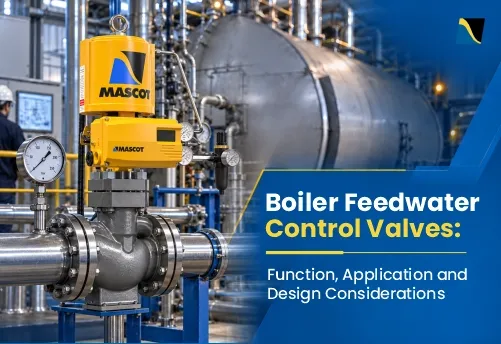
A boiler feedwater control valve regulates water flow into the boiler drum or shell to match steam demand and maintain the operating water level. Too little water can expose heat-transfer surfaces to overheating; too much can cause water carryover into the steam system and damage downstream equipment.
Feedwater service can impose high differential pressure, frequent load changes and long operating cycles on the control valve. This article explains how boiler feedwater control valves work, where they are used, and the design considerations that affect reliability from startup through full load.
A boiler feedwater control valve modulates incoming water to maintain boiler level and match steam demand. Reliable performance depends on sizing across the operating range and selecting suitable trim, materials, actuation and shutoff performance. Globe-style valves with guided trim are widely used because they provide precise throttling and accommodate specialised trims for high differential pressure.
What a Boiler Feedwater Control Valve Does
The feedwater control valve is the final control element in the boiler feedwater loop. It changes position in response to the control system so that feedwater flow follows boiler demand, opening and closing in small increments rather than switching on or off.
This discussion focuses on drum- and shell-type boilers. Once-through boilers, including supercritical units, use a different feedwater-control strategy because they do not maintain a steam-drum water level during normal operation.
Single-element control uses drum level alone. Two-element control adds steam flow measurement. Three-element control combines drum level, steam flow and feedwater flow to respond to load changes and variations in feedwater supply. During startup or very low load, the system may use single-element control until the flow measurements become reliable.
Drum Swell, Shrink and Three-Element Control
A sudden increase in steam demand can temporarily raise the indicated drum level as pressure falls and steam bubbles within the water expand, even while the boiler is losing water mass. This is known as swell. A load reduction can produce the opposite effect, or shrink. Three-element control combines steam-flow feedforward and feedwater-flow feedback with level correction, helping the system respond to the mass balance without relying on level alone.
How It Differs from Other Feedwater Valves
Several valves can appear in the same feedwater system, but they perform different functions.
| Valve | Main Function |
|---|---|
| Feedwater control valve | Modulates feedwater flow to hold drum level |
| Feedwater isolation valve | Opens or closes fully, used to isolate the line for maintenance |
| Feedwater check valve | Opens with forward flow, closes to stop backflow |
Of the three valves listed, only the control valve modulates feedwater in response to a control signal. Isolation and check valves serve shutoff and backflow-prevention functions. A separate startup control valve may regulate low-load feedwater, while the pump recirculation valve maintains minimum flow through the feed pump to protect it.
How Boiler Operating Load Changes Feedwater Valve Duty
The valve does not see the same operating condition throughout a boiler’s run. Load changes the pressure drop and flow rate it has to handle, often significantly.
Startup and Low-Load Operation
During startup, drum pressure can be low while feed pump discharge pressure remains much higher, depending on the pump and its control arrangement. The valve must then handle high differential pressure at low flow. Without suitable low-flow capacity or a dedicated startup valve, it may throttle very close to its seat.
This can be one of the most demanding parts of the duty cycle. Cavitation risk depends on inlet and outlet pressure, feedwater temperature and trim pressure recovery; sustained throttling near the seat can also accelerate local wear.
Normal and Higher-Load Operation
As boiler load rises, feedwater demand increases. The valve may handle higher flow at a lower differential pressure than during startup, depending on pump control and boiler-pressure operation. It must maintain stable modulation across these changing conditions.
Separate Startup and Main Feedwater Valves
Some boiler feedwater stations use separate startup and main valves installed in parallel, with each handling a different operating range.
A smaller valve handles startup and low-load flow, while a larger main valve handles higher loads. These are often described as a 30 percent startup valve and a 100 percent main feedwater valve, although actual capacities and the crossover point depend on the boiler and feed-pump operating envelope. Valve handover and overlap must be coordinated to avoid abrupt changes in feedwater flow or control-loop gain.
Need a feedwater valve solution that performs reliably from startup through full load?
Talk to Our Engineering TeamBoiler Feedwater Control Valve Applications
Industrial and Package Boilers
Industrial and package boilers may use a single modulating feedwater control valve, but load swings depend on process steam demand rather than boiler size alone. Larger or wider-turndown package units can still need a two-valve arrangement, so this depends on the load profile rather than boiler type alone.
Utility and Power-Plant Boilers
Large water-tube, drum-type boilers commonly run three-element control, incorporating drum level, steam flow and feedwater flow, particularly where the unit follows load rather than running at a fixed output.
High-pressure utility service can expose feedwater valves to severe startup pressure drops and large flow changes, placing demanding requirements on trim design and actuator response.
Control stability, cavitation resistance, trim durability, and actuator response become particularly important in these applications.
Combined-Cycle and HRSG Feedwater Systems
A heat recovery steam generator (HRSG) often has multiple pressure levels, each with its own feedwater control valve. Combined-cycle plants that cycle frequently, starting and stopping to follow grid demand, add thermal and mechanical cycling to the valve’s duty beyond what a base-load unit sees.
A related valve in the same system, the boiler feed pump recirculation valve, protects the pump at low flow and sees some of the highest pressure drops in the feedwater system.
Key Design Considerations for Boiler Feedwater Control Valves
Boiler Feedwater Control Valve Sizing Across the Operating Range
Evaluate startup, minimum continuous flow, normal operation and maximum boiler load as separate duty points. For each case, establish required flow, feedwater temperature and pressures at the valve inlet and outlet, accounting for intervening piping and equipment losses. Drum pressure alone may not represent valve outlet pressure.
For control valve sizing, check required Cv, predicted travel, minimum controllable flow, cavitation or choked-flow potential, and outlet velocity. Confirm body pressure-temperature rating and actuator thrust at the maximum differential pressure, including shutoff conditions. Oversizing can force the valve to operate at very low travel and impair control; a larger nominal valve is not automatically a more reliable selection.
Globe-Style Body and Guided Trim
Globe-style control valves are commonly used for demanding feedwater throttling because their linear plug movement supports controlled flow modulation and specialised trim configurations. Good stem and plug guidance also becomes important when high differential pressure creates substantial hydraulic forces.
Mascot’s GFlo – globe control valve uses two widely spaced stem guides, so the plug does not rely on the seat retainer for guidance. Its clamped-in seat ring and top-entry trim also make maintenance easier.
Stable Throttling Across Changing Loads
A feedwater valve needs to hold accurate control from low startup flow through to full load, which calls for adequate rangeability and a trim characteristic suited to where the valve sits in the control loop. The valve’s actual response in service also depends on the rest of the system, including pump head and piping losses, not the trim characteristic alone.
Equal-percentage trim produces equal percentage changes in flow for equal travel increments at constant differential pressure. It can be useful where available valve pressure drop decreases substantially as flow increases. Linear trim may be more appropriate where valve pressure drop remains relatively constant. Selection should be based on the installed response across the operating range.
GFlo offers linear and equal-percentage trim options for matching the valve characteristic to the feedwater system. Quick-opening trim is also available, but is generally not the first choice for continuous feedwater modulation.
Cavitation, Flashing and Pressure-Reduction Control
Cavitation occurs when local pressure inside the valve falls below the liquid’s vapor pressure and then recovers above it. Vapor bubbles form near the restriction and collapse as pressure recovers downstream. Repeated collapse close to metal surfaces can pit the plug, seat, trim, body and downstream piping.
Startup feedwater and pump recirculation duties can be particularly demanding because of the available pressure drop and the liquid’s vapor-pressure margin. Appropriately selected multi-stage anti-cavitation trim divides the total pressure drop into smaller stages. It can prevent cavitation when the minimum local pressure remains above vapor pressure throughout the trim. Other designs reduce damage by directing bubble collapse away from critical metal surfaces.
MASCOT’s CavFlo trim for GFlo bodies uses small passages and opposing liquid jets directed toward the centre of the retainer, locating pressure recovery and vapor-bubble collapse away from critical metal surfaces. Multi-stage CavFlo configurations also divide the pressure drop across successive restrictions; the required configuration depends on the operating conditions.
Cavitation and flashing are different phenomena: when downstream pressure remains below the liquid’s vapor pressure, some of the liquid stays vaporised downstream. Trim designed to control bubble collapse cannot eliminate flashing imposed by the system conditions; valve geometry, outlet velocity and material selection must address the resulting two-phase flow.
Facing cavitation or severe pressure drop in your boiler feedwater control valve?
Contact MASCOT ValvesPressure-Balanced Trim at High Differential Pressure
High differential pressure can create substantial hydraulic force on an unbalanced plug. Pressure-balanced trim reduces the effective unbalanced area and the thrust required to position it. GFlo offers pressure-balanced trim for suitable high-differential-pressure duties. The additional seals and close internal clearances require consideration of feedwater cleanliness, temperature and leakage requirements. Actuator sizing must still account for residual hydraulic forces, seal and packing friction, and seating force.
Trim Durability and Flow-Induced Wear
High local velocity can accelerate erosion, particularly when combined with cavitation. Hardened and erosion-resistant trim materials can improve durability under repeated severe throttling.
CavFlo trim options include stainless steel components with hardfacing, such as Stellite on the plug and seat ring. Material selection should account for temperature, water chemistry, erosion and the selected trim configuration.
Seat wear also affects shutoff. GFlo uses a self-aligning seat ring and can be configured for FCI 70-2 Class IV, V or VI leakage performance, depending on the trim and seating construction. Metal-seated Class IV or V configurations are commonly relevant to demanding feedwater duty. Class VI is generally associated with resilient seating, so its suitability must be checked against temperature and differential pressure. Leakage class describes performance under specified test conditions; it is not a guarantee of zero leakage in service.
Actuator Response and Fail Action
The actuator must hold the commanded valve position while hydraulic forces on the plug change with pressure drop and flow.
Insufficient stiffness can contribute to unstable movement, poor positioning or plug interaction near the seat. Positioner response also matters during rapid boiler load changes.
Mascot’s spring-cylinder linear actuator supplies air to both sides of the piston to provide pneumatic stiffness and precise positioning. It can operate with supply pressures up to 150 psi (10.3 bar), subject to actuator and valve configuration.
Select the required fail position from the boiler’s control and protection philosophy, considering low- and high-water risks, pump arrangements and protective trips. Specify the response to loss of instrument air, electrical power and control signal separately. Verify that the actuator can achieve the required fail action and shutoff at the worst-case differential pressure and minimum available air supply.
Maintainability and Diagnostics
Feedwater valve performance can deteriorate gradually, so plants should monitor changes in:
Digital positioners can add useful diagnostic information. Mascot’s SmartFlo positioner supports functions including auto-calibration, error diagnostics, alarms, position feedback and optional HART 7 communication.
Need help improving the reliability and response of an existing feedwater control valve?
Talk to Our TeamCommon Boiler Feedwater Control Valve Problems
| Problem | Possible Cause |
|---|---|
| Cavitation damage | Local pressure falling below liquid vapor pressure followed by pressure recovery |
| Trim erosion | High velocity, cavitation or repeated severe throttling |
| Unstable valve movement | Actuator, positioner, friction or control-loop behaviour |
| Poor low-load control | Valve operating very close to the seat or outside its effective control range |
| Seat leakage | Seat and plug wear, erosion or foreign material |
| Slow response | Actuator, positioner, air-supply or mechanical friction issues |
| Very low travel during normal load | Oversized Cv, excessive available pressure drop or unsuitable trim capacity |
| Excessive noise or vibration | Cavitation, high outlet velocity, unstable trim interaction or inadequate pressure staging |
These control valve problems should prompt a review of the valve, actuator, positioner, instrumentation and actual operating conditions rather than being treated as isolated valve faults.
Conclusion
Reliable feedwater control depends on evaluating startup, minimum, normal and maximum-load conditions and matching valve capacity, trim, materials, actuation and shutoff performance to that operating range. Globe-style valves with guided trim are widely used for demanding feedwater service because they provide precise modulation and accommodate specialised trims for high differential pressure.
Mascot Valves, ISO 9001:2015 certified and manufacturing control valves since 1972, manufactures globe control valves such as GFlo for services that include boiler feedwater, using the design principles covered here.
Need support with a demanding control valve application? Talk to the Mascot Valves team to discuss your operating conditions and valve requirements.

