


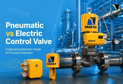
Choosing between a pneumatic and an electrically actuated control valve is not a preference question. It is an engineering decision with real consequences for response time, process safety, loop performance, maintenance intervals, availability of utilities to operate the valve and total installed cost.
Both types serve the same fundamental purpose: to convert a control signal into mechanical stem or shaft movement to regulate flow. Where they differ is in the utility they use to generate that movement, and how they operate when power or signal is lost.
This article covers the operating principles of each type, compares them across six engineering parameters, and maps each to the process applications where it performs best.
Choosing between pneumatic and electric control valve actuation depends on how the valve needs to perform in real operating conditions. This guide explains the practical differences between both options, where each one works best, and the limitations engineers need to consider. It also provides a clear selection approach for choosing the right actuator for the process.
What Is a Pneumatic Control Valve?
A pneumatic control valve is a valve body paired with a pneumatic actuator that uses compressed instrument air to generate mechanical force on the valve stem or shaft.
The pneumatic actuator is the mechanism that converts air pressure into motion. The valve body itself, across different types of control valves is mechanically compatible with either/any actuator type. Service requirements drive actuator selection, not the body style alone.
The Valve Body is Compatible With All Common Actuation Methods
Engineers often misunderstand this point. A globe control valve with a linear stem can use a pneumatic spring-cylinder actuator or an electric actuator. An Eccentric Plug Valve or Segmented Ball Valve with a rotary shaft takes a rotary spring-cylinder or rotary electric actuator.
The body is compatible with all common actuation methods. Evaluating service conditions independently drives actuator specification.
How a Pneumatic Actuator Operates
Compressed instrument air (typically 30 to 150 psi supply) drives a piston inside a cylinder against a calibrated spring. The positioner controls air flow to both sides of the piston, generating precise and stiff stem movement with high frequency response.
MASCOT’s spring-cylinder linear actuator is field-reversible between air-to-open and air-to-close by repositioning the spring and spacer. No parts replacement is required. The positioner supplies air to both sides of the piston, delivering stiff and precise movement with excellent frequency response across the full stroke range.
Single-Acting vs. Double-Acting Pneumatic Actuators
Understanding this distinction is important before specifying fail-safe behavior.
Single-acting (spring-return): Compressed air drives the actuator in one direction. The spring returns the valve to its opposite or fail position on loss of instrument air. No external energy source is needed for achieving the fail-safe position. This is a passive mechanical safety mechanism and is the standard specification for process-critical and ESD applications.
Double-acting: Compressed air drives from both sides of the piston, providing active movement in both directions. There is no internal spring required. This delivers higher torque output for large rotary valves but requires a separate fail-safe mechanism (typically a solenoid valve, volume tank, or lock-up relay) if a defined fail position is needed. Many times, providing a spring inside the cylinder of the actuator can save some accessories like volume tank or a lock-up relay.
How Control Valve with Electric Actuation Works
An electric control valve uses a motor-driven actuator to move the valve stem or rotate the shaft. The motor converts electrical energy into torque, which a gear train then transmits to produce linear travel (for globe valves) or rotary movement (for ball, butterfly, and eccentric plug valves). No instrument air is required. The valve needs only an electrical power supply and a signal cable.
The Electric Actuator Mechanism
Electric actuators accept a 4 to 20 mA or 0 to 10 V signal from the DCS or PLC. The motor drives a gear train, and a potentiometer or encoder feeds stem position back to the controller to close the position loop. The actuator requires only a power cable and signal cable at the installation point. This is an advantage where instrument air infrastructure is unavailable.
On/Off vs. Modulating Electric Actuators
This distinction is critical for actuator sizing. Specifiers frequently overlook it during the selection process.
On/off duty: The actuator moves only to the fully open or fully closed position. Limit switches hold the end positions. Suitable for isolation, block valve, and batch sequence applications.
Modulating duty: The actuator continuously adjusts position in response to a changing control signal. Standard electric motors generate heat during operation. Continuous modulation on a motor not rated for it leads to premature failure. The duty class must match the modulation frequency. IEC 60034-1 defines S4 and S6 duty ratings for frequently reversing service. Specifying a standard on/off motor on a continuous modulating loop is one of the most common electric actuator selection errors in the field.
Position Feedback and Integration with Control Systems
Electric actuators output stem position via 4 to 20 mA or digital protocols, including HART, Modbus, and Profibus. This gives direct position visibility in the DCS without a separate positioner.
MASCOT’s SmartFlo-Smart Positioner brings equivalent HART-based diagnostic capability (including valve signature and partial stroke testing) to pneumatically actuated valves. Smart positioner technology on the pneumatic side largely addresses the digital integration advantage that engineers often cite in favour of electric actuation.
Looking for HART communication in a pneumatically actuated control valve?
Talk to UsHead-to-Head Comparison: Six Engineering Parameters That Determine Selection
The actuator choice comes down to how each type performs across the parameters that matter most for your specific service. The table below summarises the six parameters covered in detail in the sections that follow.
| Parameter | Pneumatic Spring-Return | Electric |
|---|---|---|
| Response speed | 2.3 in/sec (size 25 at 60 psi); larger sizes slower | 10 to 60 seconds typical; sub-second at added cost |
| Fail-safe | Passive spring: milliseconds, no backup power needed | Requires battery, capacitor bank, or spring module |
| Positioning accuracy | ±1.0% F.S. linearity with HiFlo positioner | ±0.5% span typical with encoder feedback |
| Hazardous area (ATEX) | No electrical equipment in hazardous zone; solenoid in safe area | Ex d or Ex ia certified motor and enclosure required |
| Duty cycle | 100% continuous; no thermal limit on actuator hardware | Duty class (IEC 60034-1 S4 or S6) must be specified for continuous modulation |
| Infrastructure | Instrument air to ISA 7.0.01 quality required | Power cable and signal cable only; no compressed air |
1. Response Speed and Stroking Time
Pneumatic actuators are faster. The MASCOT spring-cylinder linear actuator delivers a stroking speed of 2.3 in/sec in the opening direction and 1.3 in/sec in the closing direction with a positioner at 60 psi supply.
Electric actuators typically require 10 to 60 seconds for full travel on modulating service. Sub-second closure is achievable only with high-speed motors and adds significant cost.
For emergency shutdown (ESD) valves and safety instrumented systems (SIS) governed by IEC 61511, the spring-return pneumatic actuator is the standard specification. Its passive mechanical fail-safe mechanism supports SIL-rated architectures. The specific SIL integrity level for the complete safety function must be validated in accordance with IEC 61508.
2. Fail-Safe Behaviour
This is where pneumatic spring-return actuation has a structural advantage over electric.
Pneumatic spring-return: On loss of instrument air, signal failure, or power failure, the mechanical spring drives the valve to its preset fail position (fail-open or fail-close) in milliseconds. No battery, no capacitor, no external energy source is required. MASCOT spring-cylinder actuators are field-reversible between air-to-open and air-to-close by repositioning the spring and spacer. No parts replacement is required.
Electric fail-safe: Requires battery backup, capacitor bank, or addition of a mechanical spring module. Battery-based systems introduce maintenance overhead and degrade over time, a genuine reliability concern for infrequently tested Emergency Shutdown (ESD) valves. Validating SIL integrity for electric fail-safe systems requires additional analysis beyond what a passive spring-return mechanism demands.
For any valve on emergency or safety-critical duty, the burden of proof sits with the electric option.
3. Positioning Accuracy and Rangeability
With the HiFlo Pneumatic Positioner, MASCOT spring-cylinder actuators achieve the following verified performance:
Independent linearity: +/-1.0% F.S.
Hysteresis: 0.5% F.S.
Repeatability: 0.2% F.S.
Deadband: 0.3% F.S.
Resolution: 0.1% F.S.
Open-loop gain: 300:1 psi/psi at 60 psi supply
Electric actuators with encoder feedback typically achieve +/-0.5% span or better and hold position with greater stiffness because there is no air compressibility. In very high stiffness throttling applications, the pneumatic positioner’s closed-loop correction handles air compressibility continuously. The 300:1 open-loop gain provides aggressive disturbance rejection.
For standard process control loops, the positioning performance of a well-tuned pneumatic positioner is more than adequate. For applications requiring extreme precision with minimal correction activity, electric actuation may offer an advantage.
4. Hazardous Area Classification: ATEX and IECEx
In ATEX Zone 1 and Zone 2 classified areas (per IEC 60079), pneumatic actuation is the standard specification because no electrical components need to be located in the hazardous zone. Instrument air tubing runs from a safe-area solenoid to the actuator. There is no spark ignition risk in the process area.
MASCOT holds ATEX Directive 2014/34/EU certification. In classified areas, pneumatic actuators with a safe-area solenoid are lower in risk, simpler to validate, and less expensive than ATEX-certified electric motors.
Electric actuators in hazardous areas require explosion-proof (Ex d) or intrinsically safe (Ex ia) certified motors and enclosures. These add cost and limit motor selection options.
The HiFlo I/P module carries FM and CSA approval for intrinsically safe operation in Class I Division 1 Groups A, B, C, D and explosion-proof rating for Class I Division 1 Groups B, C, D, providing electro-pneumatic positioner systems with a clear compliance path in hazardous areas.
5. Duty Cycle and Continuous Modulation
Pneumatic: 100% duty cycle. Compressed air does not generate heat. A pneumatic actuator can modulate continuously, repositioning every few seconds across a full shift, without any thermal constraint on the actuator’s hardware. This makes it the standard choice for temperature control loops, desuperheater spray control, and high-frequency cascade loops.
Electric: The motor generates heat during operation. Continuous modulation on a standard motor will cause overheating unless the actuator is rated for S4 or S6 duty class per IEC 60034-1. This is not a deficiency in electric actuation. It is a specification requirement that must be confirmed with the manufacturer. Failing to specify duty class correctly leads to premature field failures.
Applications running continuous modulating duty, particularly on steam service or high-correction-frequency pressure control loops, suit pneumatic actuation better unless the electric actuator carries an explicit duty class rating for the required service.
6. Installation Infrastructure and Total Cost of Ownership
Pneumatic: Requires instrument air supply filtered and dried to ISA 7.0.01 quality, distribution headers, tubing, and regulators. In plants with existing compressed air infrastructure, the incremental cost per valve is low. In greenfield remote locations without an air supply, building the infrastructure adds to the capital cost.
Electric: Requires only a power cable and signal cable at the installation point. Lower incremental installation cost in remote locations or where compressed air is unavailable. Higher actuator unit cost for equivalent thrust or torque.
Long-term operating cost depends on the usage pattern. Compressors consume energy continuously to maintain system air pressure. Electric motors consume energy only during travel. For infrequently stroking on/off valves in locations without air, electric actuation can deliver a lower total cost of ownership over a 10 to 15-year plant life.
Control valve maintenance practices also differ between pneumatic and electric actuation:
Pneumatic: seals, O-rings, tubing fittings, positioner diaphragms. Field-repairable with standard spare parts.
Electric: motor windings, gearbox lubrication, and circuit boards. Board-level failures typically require unit replacement rather than field repair.
Still deciding between pneumatic and electric actuation for your process conditions?
Talk to Our Engineering TeamThe Role of the Positioner: Where Pneumatic and Electric Actuation Converge
The positioner determines the actual control accuracy of a pneumatically actuated valve. Understanding this removes much of the apparent gap between pneumatic and electric performance in precision applications.
What a Valve Positioner Actually Does
A positioner is a closed-loop controller mounted on the actuator. It continuously compares the demanded stem position (from the control signal) with the measured stem position (from the cam-follower feedback mechanism) and adjusts air pressure to the cylinder to eliminate any error.
Without a positioner, a pneumatically actuated control valve is an open-loop device subject to packing friction, process force variation, and supply pressure changes. With a positioner, the control system corrects these disturbances in real time to improve the valve performance. The positioner is not optional for modulating service. It is the mechanism that delivers the specified accuracy.
Pneumatic (P/P) vs. Electro-Pneumatic (I/P) Positioners
Pneumatic module (P/P): Accepts a 3 to 15 psi input signal. Used in legacy plants and hazardous areas where minimising electrical signals in the process zone is a design requirement.
Electro-pneumatic module (I/P): Accepts a 4 to 20 mA input from the DCS and converts it internally to a pneumatic output to the actuator cylinder. Standard for modern DCS and PLC integration.
MASCOT’s HiFlo-Pneumatic Positioner accepts both modules interchangeably. A P/P module can be replaced with an I/P module in the field without remounting or recalibrating the positioner body. Both modules achieve identical positioning performance: ±1.0% linearity and 0.2% repeatability. The signal type does not change the fundamental accuracy. Standard signal ranges of 4 to 20 mA (I/P) and 3 to 15 psi (P/P) are supported, with optional ranges. All models can be calibrated for 2-way or 3-way split range service.
Smart Positioners and Diagnostics (HART Protocol)
MASCOT’s SmartFlo-Smart Positioner communicates over HART and provides valve signature capability, comparing the current actuator response curve against the baseline to detect trim wear, seat damage, or increasing packing friction without removing the valve from service.
Partial stroke testing (PST) via smart positioner verifies ESD valve functionality during operation without full closure, maintaining SIL compliance on running processes.
Smart positioner technology on a pneumatic actuator provides the same level of digital diagnostics and DCS integration that engineers often cite as a reason to choose electric actuation. The two technologies converge at the positioner level.
Application Mapping: Which Actuator Type for Which Process
The right actuator type becomes clear when you match the engineering requirements to the process.
Oil and Gas: Upstream, Midstream, Refining
Hazardous area classification (Zone 1, Zone 2) makes pneumatic spring-return the default for production and processing valves.
ESD valves on wellheads and separator outlets require sub-second closure and a passive fail-safe. Pneumatic spring-return with a safe-area solenoid is the standard.
High-cycle separator-level and choke control loops run continuous modulation duty. Pneumatic actuation with the HiFlo positioner handles 100% duty cycle without thermal limitation.
Gas metering and SCADA-integrated stations use electro-pneumatic (I/P) positioners or SmartFlo for remote diagnostics and HART communication, while retaining pneumatic fail-safe behaviour.
Power Generation: Feedwater, Steam, and Extraction
High-thrust requirements on large-bore feedwater control valves favour spring-cylinder actuation. MASCOT’s linear actuator supports supply pressures up to 150 psi and is available in piston areas from 25 to 600 sq. in. (including tandem double-piston configurations for the 400 and 600 sq. in. sizes), covering high-thrust duties on large globe valves.
Desuperheater spray control using the DeFlo-VSD Variable Spray Desuperheater requires continuous proportional control over an 80:1 turndown range. The actuator must support continuous repositioning without thermal limitation. Pneumatic is the correct actuator type here.
Electric actuation is applicable on isolation valve duty (on/off, infrequent) in turbine buildings where instrument air headers are not available.
Petrochemical and Chemical Processing
Reactor outlet discharge using the flush bottom valve is available with pneumatic spring-cylinder or electric single/three-phase actuation. For batch discharge sequences controlled by PLC, electric actuation integrates directly. For safety-critical reactor isolation, spring-return pneumatic is the standard.
High-pressure drop letdown stations using the globe control valve with cavitation control trim or noise attenuation trim run continuous modulating duty and require high-thrust actuation with a reliable fail-safe. Pneumatic spring-cylinder is the default.
Slurry and erosive service on the EFlo and VFlo uses MASCOT’s rotary spring-cylinder actuator. For Tungsten Carbide-trimmed valves where fail-safe closure is required, pneumatic spring-return is specified.
Pharmaceutical, Food, and Clean Process
Instrument air quality becomes a selection variable in these industries . Air contaminated with compressor oil can affect product purity. ISO 8573-1 Class 1 oil-free air is required where instrument air contacts clean process areas.
Electric actuation removes the compressed air system from the process zone entirely and simplifies sanitary design in CIP (clean-in-place) environments. For dosing and blending applications requiring tighter positioning repeatability, electric actuators with encoder feedback offer an advantage. For flow-critical loops with continuous modulation, verify the electric actuator’s duty class rating before specifying.
Need the right actuator and positioner combination for your process application?
Talk to Our Engineering TeamA Practical Decision Framework for Engineers
Selecting an actuator should never begin with the question, “Electric or Pneumatic?” It should begin with a clear understanding of the application.
The following five questions help identify the most appropriate actuator technology for the duty, environment, and control philosophy.
| Question | If the Answer Is… | Recommended Choice | Engineering Rationale |
|---|---|---|---|
| 1. Is the valve located in a hazardous area? | ATEX Zone 1 or Zone 2 | Pneumatic spring-return | Offers a proven, lower-risk solution with simpler hazardous-area compliance. Although ATEX-certified electric actuators are available, they generally increase cost, enclosure complexity, and maintenance requirements. |
| 2. What fail-safe action and response time are required? | Sub-second closure, emergency shutdown, or SIL-rated duty | Pneumatic spring-return | Delivers rapid, predictable fail-safe operation without relying on stored electrical energy. |
| Fail-in-place acceptable and response time greater than 30 seconds | Electric actuator | Suitable where rapid shutdown is not critical, provided the backup system satisfies the required SIL integrity. | |
| 3. Is the valve continuously modulating or primarily on/off? | Continuous throttling or control duty | Pneumatic actuator | Provides unlimited duty cycle, excellent positioning performance, and no motor thermal limitations. |
| Infrequent on/off operation | Either technology | Electric actuators can reduce long-term operating energy where movement is infrequent. | |
| 4. Is instrument air available at the installation point? | Existing instrument air supply | Pneumatic actuator | Makes use of existing plant infrastructure with minimal additional installation cost. |
| No instrument air available | Electric actuator | Eliminates the need for compressors, air headers, tubing, and associated maintenance. | |
| 5. What are the control system and diagnostic requirements? | Standard 4–20 mA control | Either technology | Both integrate seamlessly with modern DCS and PLC systems. |
| HART communication, valve signature, and advanced diagnostics | Either technology | Smart electro-pneumatic positioners provide the same digital functionality as electric actuators while retaining pneumatic performance. |
The MASCOT HiFlo-positioner’s electro-pneumatic module is field-interchangeable with the pneumatic module. The same positioner body, cam, and feedback mechanism serve both signal types. Upgrading a plant from pneumatic signal to 4 to 20 mA control requires only a module swap, not a positioner replacement.
Conclusion
The actuator choice on a control valve is a specification decision, not a preference. Pneumatic spring-return actuation with an electro-pneumatic positioner remains the standard for the majority of process industry applications because it satisfies fail-safe, hazardous area compliance, duty cycle, and DCS integration requirements within a single, field-maintainable package.
Electric actuation is the correct choice where instrument air is genuinely unavailable, modulation frequency is low and continuous duty is not required, and direct encoder-based positioning without a positioner is preferred.
In most plants, both types coexist: pneumatic on process control, ESD, and safety-critical loops; electric on isolation duty and remote on/off applications. Getting the boundary right at the specification stage avoids costly field modifications later.
For actuator selection support or to speak with an engineer about your application, contact MASCOT Valves at www.mascotvalves.com
FAQ’s
1) When should I specify a spring-return pneumatic actuator rather than electric?
Specify pneumatic spring-return when the valve is in a hazardous area (ATEX Zone 1 or Zone 2), when the application requires a passive fail-safe with sub-second response, or when the loop runs continuous modulating duty. These three conditions cover the majority of process control, ESD, and safety-critical applications in oil and gas, power, and petrochemical plants.
2) What is the difference between a P/P and an I/P positioner?
A P/P (pneumatic-to-pneumatic) positioner accepts a 3 to 15 psi input signal and outputs a pneumatic pressure to the actuator. An I/P (current-to-pneumatic) positioner accepts a 4 to 20 mA input from the DCS and converts it internally to a pneumatic output. The MASCOT HiFlo positioner accepts both modules interchangeably on the same body, achieving identical accuracy with either signal type.
3) Can a continuously modulating loop use an electric actuator?
Yes, provided the actuator carries a duty class rating appropriate for the modulation frequency. IEC 60034-1 defines S4 and S6 duty classes for frequently reversing electric motors. A standard on/off rated motor will overheat on a continuous modulating loop. Confirm the duty class rating with the manufacturer before specifying.
4) Do MASCOT pneumatic actuators support HART diagnostics?
Yes. The SmartFlo Smart Positioner communicates over HART and provides valve signature capability, comparing actuator response curves against the baseline to detect trim wear, seat damage, or packing friction without removing the valve from service. Partial stroke testing (PST) for ESD valve verification is also available through the SmartFlo positioner.
5) What instrument air quality does a pneumatic control valve require?
Instrument air must meet ISA 7.0.01 quality: clean, dry, and oil-free. In pharmaceutical and food processing applications where instrument air contacts clean process areas, ISO 8573-1 Class 1 oil-free air is required. Electric actuation eliminates the instrument air requirement entirely, which can simplify the design of clean process and sanitary environments.

