


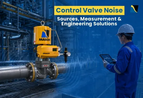
A noisy control valve is rarely just a noise problem. In most cases, the sound is a symptom of something happening inside the valve or the connected piping: excessive pressure drop, high velocity, cavitation, flashing, or a valve that was selected on line size rather than actual service conditions. Engineers who treat the noise instead of the cause often find the sound returns, sometimes with additional damage to trim, seats, or piping.
This article explains where control valve noise comes from, how it is measured and predicted against IEC standards, and which engineering approaches actually address it at the source rather than masking it downstream.
Control valve noise comes from three distinct mechanisms (mechanical, aerodynamic, hydrodynamic). It is measured and predicted using IEC 60534-8-2, 8-3 and 8-4, checked against occupational limits such as OSHA 1910.95, and reduced primarily through correct sizing, staged trim design, and, only when needed, path treatments like diffusers or insulation.
What Is Control Valve Noise and Why Does It Matter?
Control valve noise is generated when pressure energy converts into turbulence, vibration, and acoustic energy as fluid passes through the restriction inside the valve. Sound levels are typically expressed in dB(A), the A-weighted scale used because it reflects how the human ear responds to different frequencies, and it is the scale referenced in most occupational noise standards.
Noise matters for two separate reasons. The first is hearing safety for personnel working near the valve. The second, often overlooked, is what the noise indicates about the valve’s internal condition.
Persistent high-frequency noise, rattling, or vibration can indicate broader control valve problems, including cavitation damage, trim erosion, or an unstable control loop, not just an acoustic nuisance. A valve can be sized correctly for Cv and still generate unacceptable noise if velocity, pressure ratio, or trim selection were not evaluated alongside sizing.
What Causes Noise in a Control Valve?
Control valve noise can originate from mechanical vibration, compressible gas flow, or liquid-flow effects. Identifying the source is essential because each mechanism requires a different engineering solution.
Mechanical Vibration and Flow-Induced Noise
Mechanical noise occurs when valve components, such as the plug, stem, or trim, vibrate due to unstable flow forces, loose parts, resonance, or actuator instability. This type of noise is a structural issue rather than a purely acoustic one.
Insulation or downstream treatment will not resolve it, since the vibration originates inside the valve or its supporting structure. Identifying and correcting the mechanical cause, whether it is worn guiding, an undersized actuator, or resonance in the piping, is the only reliable fix.
Aerodynamic Noise in Gas and Steam Service
Aerodynamic noise develops when gas or steam accelerates through the valve restriction and forms high-velocity turbulent jets. It becomes significant in high-pressure-drop gas service, steam letdown, venting, and compressor anti-surge applications.
As velocity at the vena contracta approaches sonic conditions, turbulence and noise increase sharply. Inlet and outlet pipe velocities alone do not always reveal this risk, since the highest velocity occurs within the trim passages and at the vena contracta.
Hydrodynamic Noise in Liquid Service
Hydrodynamic noise results from turbulence, cavitation, or flashing in liquid flow. It is particularly important to evaluate closely because it often signals physical damage risk rather than just sound. Cavitation-related noise is commonly described as a rattling or gravel-like sound in the pipe, caused by the collapse of vapor bubbles after pressure recovers above vapor pressure.
Looking for an engineering solution to mechanical, aerodynamic, or hydrodynamic valve noise?
Talk to Our Engineering TeamCavitation, Flashing and Choked Flow: Why They Must Be Separated
These three conditions are often discussed as if they were the same problem. They are not, and treating them the same way leads to the wrong fix being applied.
| Condition | What Happens | Main Risk | Typical Fix |
|---|---|---|---|
| Cavitation | Pressure drops below vapor pressure, then recovers | Bubble collapse, pitting, vibration | Anti-cavitation trim, staged pressure reduction |
| Flashing | Pressure drops below vapor pressure and does not recover | Continuous two-phase erosion downstream | Hardened trim, outlet velocity control |
| Liquid choking | Vapor formation limits further flow increase | Noise, instability, capacity error | Recheck sizing with valve-specific recovery data |
| Aerodynamic choking | Gas reaches limiting velocity through the restriction | High sound pressure level, acoustic fatigue | Low-noise trim, staged pressure reduction |
Cavitation is fundamentally a damage mechanism caused by bubble collapse after pressure recovers. Flashing is a continuous two-phase condition because pressure never recovers above vapor pressure downstream. Confusing the two often leads engineers to specify anti-cavitation trim for a flashing service, where hardened materials and outlet velocity control are the more appropriate response.
Also Read: Mitigating Cavitation and Flashing: Practical Trim Solutions with Mascot Valves
Regulatory and Allowable Noise Limits
There is no universal maximum noise limit for every control valve installation. The allowable level depends on the project specification, measurement location, operating condition, worker exposure duration and applicable national regulations.
In the United States, OSHA sets an eight-hour permissible exposure limit of 90 dBA and requires a hearing conservation programme when exposure reaches an eight-hour time-weighted average of 85 dBA. NIOSH recommends an occupational exposure limit of 85 dBA over eight hours.
The European noise directive sets lower and upper exposure action values of 80 and 85 dB, with an exposure limit of 87 dB after accounting for hearing protection.
These occupational limits should not be treated as automatic control valve noise guarantees. The project specification should separately define the allowable sound level, measurement distance and operating conditions during the valve selection stage.
How Control Valve Noise Is Measured and Predicted
IEC 60534-8-3: Aerodynamic Noise Prediction
IEC 60534-8-3 provides a theoretical method for predicting the external sound pressure level generated by compressible fluid flow through control valves and adjacent piping. It applies to single-phase dry gases and vapors and covers several types of control valves, including globe, butterfly, rotary plug, and ball valves.
IEC 60534-8-4: Hydrodynamic Noise Prediction
IEC 60534-8-4 predicts noise generated by liquid flow through a control valve, accounting for both normal turbulence and cavitation. The resulting noise level is calculated at a defined position downstream of the valve and outside the pipe wall.
IEC 60534-8-2: Laboratory Measurement of Hydrodynamic Noise
IEC 60534-8-2 sets out the laboratory method for measuring sound pressure level generated by liquid flow through control valves, including the identification of cavitation onset. This standard supports the prediction methods used in IEC 60534-8-4 by providing tested, repeatable reference data.
Occupational Noise References
Alongside the IEC prediction standards, occupational references such as OSHA 1910.95 define the exposure thresholds that ultimately determine whether a predicted noise level is acceptable for personnel working nearby. These references do not replace the IEC prediction methods. They define the target the prediction is measured against.
Looking for the correct trim strategy for damaging liquid or high-noise gas service?
Contact Our Engineering TeamEngineering Solutions for Control Valve Noise Reduction
1. Start With Source Control Before Path Control
Noise should be addressed first at the point where it is generated inside the valve. Path treatments, such as insulation or silencers, can reduce the sound reaching personnel, but they do not remove the internal cause.
As a general rule, correcting the valve or trim should be the first step, with path treatment reserved for cases where source correction alone is not sufficient or the existing valve cannot be replaced.
2. Correct Valve Sizing and Trim Selection
Noise can increase significantly when a valve is oversized or selected based on line size rather than actual flow conditions. An oversized valve operating close to shutoff produces higher local velocity and poor travel range at normal flow, which can also lead to controller hunting and premature seat wear. Evaluating minimum, normal, and maximum flow conditions during sizing, not just the maximum case, is essential for improving control valve performance and avoiding self-inflicted noise problems.
3. Pressure-Drop Staging
Rather than taking the full pressure drop across one restriction, staged trim designs divide the pressure reduction into multiple smaller steps. This reduces the pressure drop handled at each stage, lowering turbulence and the acoustic energy generated. Staging is particularly relevant in high-pressure-drop gas, steam, and severe liquid services.
4. Flow Division Through Multi-Path Trim
Flow division splits a single large, turbulent jet into many smaller flow streams. Smaller streams carry less turbulent energy individually, and the resulting noise is often shifted toward frequencies that are easier to attenuate through the pipe wall.
5. MegaFlo Noise Attenuation Trim for Gas and Steam Noise
Mascot’s MegaFlo trim is designed for high-pressure-drop gas and steam applications where aerodynamic noise is a concern. It reduces pressure gradually across a series of stages rather than allowing most of the pressure drop to occur at the vena contracta, and it divides flow into multiple smaller streams to reduce turbulent energy. Selection should always be based on actual process data and Mascot’s trim-specific performance information rather than a general noise reduction assumption.
6. CavFlo Cavitation-Control Trim for Liquid Noise and Damage
Mascot’s CavFlo trim addresses cavitation in liquid service by using multiple small holes through the seat retainer. As the plug lifts, opposing jets of liquid impinge at the center of the retainer, moving vapor bubble collapse away from critical metal surfaces. This reduces cavitation damage to the trim and body. CavFlo should be understood as a damage-control solution for cavitating service, not a general-purpose noise treatment for every liquid application, and it requires reasonably clean service conditions due to the close clearance between plug and retainer.
7. Downstream Piping and Outlet Velocity Control
Noise generation does not stop at the valve outlet. Outlet velocity, whether expressed as Mach number for gas and steam or as linear velocity for liquids, continues to influence noise and erosion in the piping immediately downstream.
Reducers, elbows placed too close to the valve outlet, and abrupt changes in pipe geometry can all amplify noise that would otherwise be manageable. Reviewing downstream layout alongside valve selection, rather than as a separate piping decision, helps avoid noise problems that a correctly selected valve alone cannot solve.
8. Path Treatments: Diffusers, Insulation, Silencers and Enclosures
When source treatment alone is insufficient, or when an existing valve cannot be replaced, several path treatments are available. Inline diffusers divide the total pressure drop between the valve and a downstream device, lowering the pressure ratio the valve itself must handle.
Increasing pipe wall thickness improves transmission loss but adds complexity to piping design. Acoustic or thermal insulation can be effective when correctly applied, though it carries a known risk of corrosion under insulation (CUI), which is one reason plant maintenance teams are often cautious about it.
Inline silencers and acoustic enclosures address noise after it has already left the valve. Path treatment can lower the noise reaching personnel, but it does not eliminate cavitation damage, flashing erosion, or a mechanical vibration source inside the valve.
Need help selecting between MegaFlo, CavFlo and downstream noise-control measures?
Talk to MASCOT ValvesMatching the Solution to the Application
| Application | Noise or Damage Mechanism | Relevant Approach |
|---|---|---|
| High-pressure-drop gas or steam | Aerodynamic noise, high velocity | GFlo with MegaFlo noise attenuation trim |
| Cavitating liquid service | Vapor bubble collapse, trim and body damage | GFlo with CavFlo cavitation-control trim |
| General liquid or gas throttling | Standard noise review during sizing | GFlo – Globe control valve |
| Dirty, viscous, or slurry media | Erosion, clogging, unstable throttling | EFlo or VFlo, depending on service conditions |
| High flow, lower pressure drop | Large-flow throttling duty | DiskFlo where application permits |
Conclusion
Control valve noise should be treated as diagnostic information and an energy-management problem, not simply as sound that needs to be contained.
Engineers should first determine whether the source is mechanical, aerodynamic or hydrodynamic, then evaluate valve sizing, pressure ratio, cavitation or flashing risk, trim geometry, outlet velocity and downstream piping. Multi-stage and multi-path trims can reduce noise at its source, while insulation, silencers and enclosures provide secondary attenuation where required.
MASCOT Valves manufactures control valves and severe-service trims for gas, steam and liquid applications. For support with valve sizing, noise prediction or severe-service trim selection, contact us with the complete process conditions.
FAQ
1) What is the difference between a noise attenuation trim and an anti-cavitation trim?
A noise attenuation trim, such as MegaFlo, manages gas or steam velocity and turbulence to reduce aerodynamic noise. An anti-cavitation trim, such as CavFlo, controls where vapour bubbles collapse in liquid service to prevent physical damage. They address different mechanisms and are not interchangeable.
2) Can a correctly sized control valve still generate excessive noise?
Yes. Cv sizing confirms the valve can pass the required flow, but it does not by itself account for velocity, pressure ratio, or trim geometry. A valve can be correctly sized for capacity and still exceed noise limits if these factors are not evaluated separately.
3) Does pipe schedule (wall thickness) actually reduce control valve noise?
Increasing pipe wall thickness can improve acoustic transmission loss and reduce externally radiated sound. The actual reduction depends on pipe diameter, material, wall thickness, frequency spectrum and surrounding insulation. It does not reduce the noise generated inside the valve; it only reduces the amount radiated through the pipe wall, so it should not replace source control.
4) Can control valve noise damage downstream piping?
Yes. High-energy aerodynamic noise and flow-induced vibration can excite downstream piping, supports and small-bore connections. Over time, repeated cyclic stress may contribute to fatigue failure, even when the measured personnel noise level meets the project limit.
5) What is the maximum allowable noise level for a control valve installation?
There is no universal maximum noise level for every control valve installation. The allowable level must be defined by the project or plant specification, including the operating condition, measurement position and distance from the valve or pipe. Occupational exposure limits such as OSHA and NIOSH values apply to cumulative worker exposure and should not be treated as automatic control valve noise guarantees.

